Page17
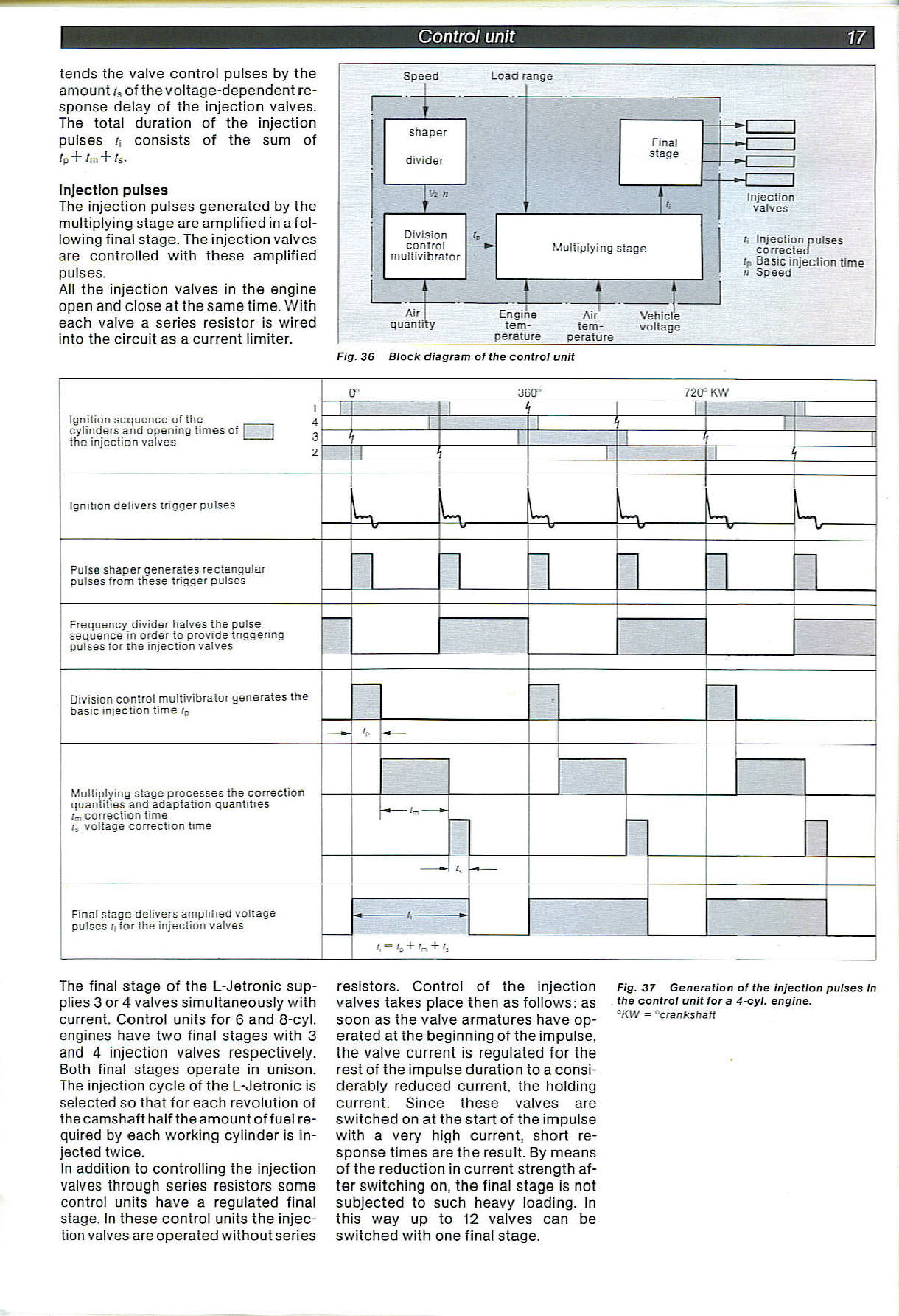

Fig. 36 Błock diagram of the control unit
tends the valve control pulses by the amount ts of the voltage-dependent re-sponse delay of the injection valves.
The total duration of the injection pulses t, consists of the sum of
/p "h /m "h ts.
Injection pulses
The injection pulses generated by the multiplying stage are amplified in a foliowi ng finał stage. The injection valves are controlled with these amplified pulses.
Ali the injection valves in the engine open and close at the same time. With each valve a series resistor is wired into the Circuit as a current limiter.
Ignition sequence of the l_
cylinders and opening times of ; ;
the injection valves
|
0= 360= 720= KW | |||||
|
1 |
i i | ||||
|
I |
i |
i | |||
|
zr |
i | ||||
Ignition delivers trigger pulses
w
K
W
L
Pulse shaper generates rectangular pulses from tHese trigger pulses
Frequency divider halves the pulse sequence in order to provide triggering pulses for the injection valves
Diyision conirol multivibrator generates the basie injection time rD
Multiplying stage processes the correction quantities and aaaptation quantities correction time r5 voltage correction time
- U
Finał stage delivers amplified voltage pulses r for the injection valves
r, = r0 + /„ +1.
The finał stage of the L-Jetronic sup-plies 3 or 4 valves simultaneously with current. Control units for 6 and 8-cyl. engines have two finał stages with 3 and 4 injection valves respectively. Both finał stages operate in unison. The injection cycle of the L-Jetronic is selected so that for each revolution of the camshaft half the amount of fuel re-ąuired by each working cylinder is in-jected twice.
In addition to controlling the injection valves through series resistors some control units have a regulated finał stage. In these control units the injection valves are operated without series resistors. Control of the injection valves takes place then as follows: as soon as the valve armatures have operated at the beginning of the impulse, the valve current is regulated for the rest of the impulse duration to a consi-derably reduced current, the holding current. Since these valves are switched on at the start of the impulse with a very high current, short re-sponse times are the result. By means of the reduction in current strength af-ter switching on, the finał stage is not subjected to such heavy loading. In this way up to 12 valves can be switched with one finał stage.
Fig. 37 Generation of the injection pulses in the control unit for a 4-cyl. engine.
QKW = Ccrankshaft
Wyszukiwarka
Podobne podstrony:
Boguckip Z. Bartoń Schemat blokowy 3 wzajemnie połączonych systemów Fig. 1. Błock diagram of 3-area
P1020412 3. The błock diagram of a simple example Computer with microprogrammed contro! (presented o
P1020415 Figurę 3.1. The błock diagram of a simple Computer with hardwired control. 0000 0001 INA
6 (388) ?=• FIGURĘ 13-16 Błock diagrams of (<?) a dojne and {b) a hasin. Notę that m a domc the o
snap 2 Błock Diagram of DSPRX by DL6iAK
Błock diagram of G3WXO s phaae-locked 2m
2` CIRCUIT OPERATION Figurę 5 shows a błock diagram of the FM wireless microphone Circuit The microp
92 Fig. 4. The results table for calculated CCT diagram of a Steel of the following Chemical composi
5 (434) (a) Figurę 13-15 Piuugmc fol*. (:ł) A schcmanc lilustration of a plunging fold. (4) A błock
(c) Explain the working of DVD-ROM with the hełp of błock diagram. 4 5.
Algorithm representation Graphical methods: llowcharts, błock diagrams, schemes Formal languages: sa
60 B. Zieliński Rys. 1. Schemat cyfrowego systemu radiokomunikacyjnego Fig. 1. Diagram of digital ra
więcej podobnych podstron