77289 p36 (16)


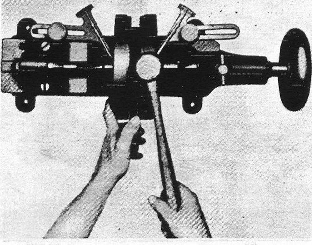
ILLUS. 25
TRUING FLYWHEEL MAINSHAFTS
play. If this is done, backs of retcriners may also need to be ground off slightly as retainer assembly must, in every case, be narrower than forked rod.
After rod sideplay has been checked and adjusted, crank pin nut pulled very tight and nut lock washer fitted, again install wheel assembly in truing device and recheck for trueness.
Caution: After flywheels and rods are assembłed, make finał check to be surę oil passage is open to rod bearing. Apply compressed air to hole in side of pinion shaft, near its outer end, and observe that air escapes around connecting rod lower end. If this passage becomes blocked in some manner and engine is assembłed and put in service with it blocked; engine will get no lubrication, except in timing gear case. This is not likely to be detected until serious damage has been done, as the oil cir-culation indicator in instrument panel will give no waming when the oiling system is blocked in this passage.
Truing Flywheels
Bear in mind that, while a straight-edge across rim faces is used when assembling flywheels to keep them as near as possible true with each other, fińal truing is a matter of truing sprocket shaft and pinion shaft to perfect alignment with each other, rather than truing flywheel rims. Install wheel assembly in truing device (manufacturers number 11962-X) and adjust so that centers are just snug (wheels must tum freely). If flywheel assembly is either loose between centers or is sąueezed, indicators will not indicate accurately. Indicators should be adjusted as closely as possible to flywheels, and 'so that pointers rest about in the middle of graduated scales.
Tum flywheels and observe the movement of indicator pointers. Movement of pointers toward flywheels indicates high points of shafts. Find highest point of each shaft and mark flywheel rims at those points. Loosen device centers slightly, just enough so it can be detected that flywheel assembly is a trifle loose. Tum high point of first one flywheel and then the other to the top and strike rim of wheel one or morę sharp blows with a lead or copper hammer. The number of blows reąuired and how hard they should be depends, of course, on how far shafts are out of true. Remember that device centers should be loosened slightly before striking flywheels. However, they should not be loosened to the extent of allowing flywheels considerable play between centers, as making them very loose is likely to result in broken or damaged centers.
After striking wheels with hammer as explained above, readjust device centers to just snug and again tum wheels and check with indicators. Repeat the truing operation until indicators show within .001" of true. Each graduation on indicator scalę is approx-imately .002"; therefore, when shafts are true within reąuirements, neither indicator will move morę than about one-half graduation.
In the case of a flywheel assembly that is con-siderably out of true and which cannot be trued up by following the procedurę described, it may be due to crack at one of the flywheel shaft holes or a damaged and enlarged tapered hole. If used sprocket and pinion shafts are assembłed in flywheels, it may be due to one of these shafts being wom consider-ably out of round at the point where indicator takes bearing against it.

Flywheels are now ready to be assembłed into crankcases which have already been given due attention as concems main bearing fitting, (See "Fitting Main Bearings," Page 34). A strong rack or box with an opening about 8"x 8" and at least 4" deep should be avcdlable, on which to place right crankcase on its side. Insert bearing washer and bearing in the order shown in Illustration 28.
Select two flywheel thrust collars (Item 12). Place thrust collars over sprocket and pinion shafts and fit them on flywheel hubs. Be surę they register on dowel pins and seat fully against wheel faces. These collars come in various thicknesses to permit adjust-ing flywheel endplay between crankcases. The only way to determine exactly what collar thickness is reąuired is to try one set and then another until the correct endplay is attained. The average thickness of collars used in new engine assembly is about .080". Both collars should be approximately the same thickness in order to keep flywheels centered in crankcases and connecting rod upper ends centered between piston bosses.
When a set of collars has been selected and installed on wheels, fit flywheel assembly into right crankcase. Install roller bearing and bearing washer on sprocket shaft in the order shown in Illustration 28, and install left crankcase. No gasket is used on crankcase center joint, and joint should not as yet be shellacked. Insert the two cap screws at top of cases and two studs .at bottom of cases and tighten to clamp cases securely together.
Now, by pushing back and forth on ends of sprocket and pinion shafts, check flywheel endplay. If no endplay is found, cases will have to be taken aport and thinner thrust collars fitted. Reassemble and again check endplay. If it is found that flywheels now have endplay, check with flywheel endplay gauge (manufactureris tool number 11967-38) and a thickness gauge to determine just how much play exists. When this has been accurately deter-mined, it is then a simple matter to calculate how
36
Wyszukiwarka
Podobne podstrony:
skanuj0004 4 44. Oblicz: a)
Vous avez entre 16 et 25 ans ?Peu ou pas de dipldme, vous cherchez un emploi ?Les emplois d’avenir s
2) narysować prostokąt o wymiarach 16 cm x 25 cm- będą to ściany zewnętrzne zakład
S 8 10 11 12 23 24 la 16 13 14 15 i i 16 17 25 13a 14 a 15a 16a 17a 26 18
DUNAJECN130c9705328 miejsce na nadrukSI W /i 1 2 3 4 5 6 7 8 9 10 11 12 13 14 15 16 17 18 19 2
312 (16) 624 25. Obwody nieliniowe prądu okresowego W stanie jałowym transformatora z uzwojeniem wtó
320 (16) 640 25. Obwody nieliniowe prądu okresowego Rys. 25.50. Układ realizujący podwojenie
325 (16) 650 25. Obwody nieliniowe prądu okresowego 25.13.2. Obwód zawierający dwa prostowniki W obw
9 (1349) Ketu i Liczba 7 Ketu jest obiektem rządzącym ludźmi urodzonymi 7. 16 lub 25 dnia miesiąca o
Uczciwek012 Wyłączniki są produkowane na prądy znamionowe: 8,10,13,16,20, 25, 32, 40, 50, 63 A. Wyłą
7-8.11 15-16.11 25-26.ll r 28.ll-l.lllINFORMATORLUTY 20193rd HBP Student Conference On
48 (227) Sd Kfz 251/16 Ausf. D z 25. Pułku Grenadierów Pancernych SS, Belgia, wiosna 1944 roku. Sd K
021 (21) Graniastostupyj Z twierdzenia Pitagorasa otrzymujemy: 42 + 32 = a -16 + 9 = n2 25 = a2
więcej podobnych podstron