2949775925
275
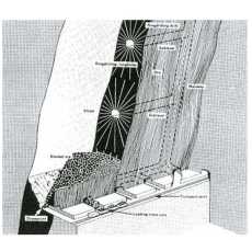
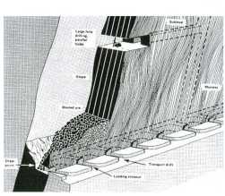
Fig. 1. Schematic illustration of A (left): ring drilling, B (right): parallel drilling Rys. 1. Ilustracja schematyczna A (z lewej): wiercenie pierścieniowe, B (z prawej): wiercenie równoległe
the first stage to implement Parallel drilling system. If so production drift’s sides are excavated in width up to thickness of the ore body. Blast holes diameter in parallel drilling is between 105-165 mm with lengths up to 90 m. The performance of the drilling system in this respect is about 50 m in a shift. Also ore production rangę of drilling and blasting related hole lengths is between 8-18 m3/m (Fig. IB).
In this case blast holes are drilled in bottom of the production drifts downward to draw points. In generał the inclination of blast holes equals the maximum dip of the ore body. Large diameter Longholes with large scalę blasting have been specified in this drilling pattern. This specification is the main cause to appear mass production in sublevel stoping method. Production drifts distance in a vertical alignment in order to implement this system is over 50 meters commonly. Although excavation of one production drift at the top of the open stopę is a typical designation. In this case length of the blast holes is defined as the distance of bottom of a production drift to undercutting space. Therefore by execution parallel drilling system, development of production drifts gets the lowest doable cost ratę. Also spacing and burden of blast holes regarding large diameter in parallel pattern get to the largest possible rangę in underground production drilling. Therefore total length of the holes in an open stopę reaches to least amount achievable ratę. In order to application of high pressure DTH jumbos, economical condition of sublevel stoping has been changed in the recent decades. Regarding appearance this convenience sublevel stoping has been found morę attractive application.
Furthermore there are some other type of long hole drilling pattern which have created of combined parallel and ring drilling properties as underhand fan drilling by DTH jumbos. As a case in El Soldado minę underhand fan pattern has been implemented with blast holes’ diameter 165 mm and length 80 m by DTH system (Contador, Glavic 2001). High pressure DTH hammers in parallel drilling system have the highest ratę of drilling’s accuracy. Inaccuracy of this eąuipment is less than 2% up to 120 m hole length of the blast hole in generał (Haycocks, Aelick 1992).
Wyszukiwarka
Podobne podstrony:
281 281 L1=6 L2=6.3 L3=7.2 L4=7.6 L5=5.7 L6=4.7 L7=4.3 Fig. 3A (left): ring drilling (vertical
CR4 a fig. 1. Schematic diagram of the rf wattmeter for 1 to 500 MHz. Fixed-value capacitors ar
169 169 Sprooawe prouki Ti. C, Al Rys. 1. Schemat metody syntezy SHSB Fig. 1 Schematic representatio
-9 Rys. 3. Schemat pomiaru metodą dwusiecznych jednego poziomu z jednego stanowiska Fig. 3. The sche
Boguckip Z. Bartoń Schemat blokowy 3 wzajemnie połączonych systemów Fig. 1. Błock diagram of 3-area
30 TRIBOLOGIA 6-2012 Rys. 3. Schemat stanowiska badawczego T-01M po modyfikacji Fig. 3. Schemat
Zdjęcie065(5) Fig. 4. Schemacie model for formation of che Zcchstein polymeullic mincralizaiion in »
Andrzej Szlęk Rys.6.3. Fig.6.3. Schemat umiejscowienia końcówki termopary w ziarnie paliwa Scheme of
Przegląd Geologiczny, vol. 55, nr 12/1, 2007 Fig. 13. Schematic map of oil and gas fields in the Car
280 In Figurę 2 the pattem of ring drilling respecting thickness: 35 m, height: 90 m in a vertical c
Easy Tatting (31) Fig. 4. 6. Smali ring (3 = 3 = 3 + 3) Join to picots of thi
więcej podobnych podstron