7884079553
NPL Report MATC(A) 164
Finał polishing of the samples was carried out by hand using a gamma aluminide powder suspcnded in lapping fluid (OP-S).
When etching of the samples was reąuired, for example to highlight microstructure, the following procedures were uscd:
Lead based solders: a solution containing 2 ml hydrochloric acid and 98 ml industrial
methylated spirits in a polish-etch techniąue, employing 0.25pm diamond pastę as the polishing medium.
Lead-free solders: 2 ml nitric acid, 2 ml hydrochloric acid and 96 ml distilled water in a polish-etch techniąue, with 0.25pm diamond pastę as the polishing medium. For satisfactory results a very short polish cycle (2 sec) was applied followed by immediate specimen wash in distilled water.
Acceptable images highlighting joint microstructure were obtained using an optical microscope, whereas cracks in the solder joints were usually better located using an SEM in the secondary electron modę. However, the SEM techniąue does reąuire a conductn e coating (e.g. AuPd, Au or carbon) over the specimen. The level of polishing was minimised by examining the specimens in the SEM back scattered electron modę, which is well suited for qualitative and/or quantitative analyses. A techniąue called "digimap” (i.e. mapping selected elements in distinguishable colours) also proved to be helpful when used in applications with coatings and laminate.
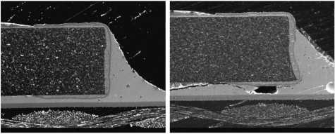
Figurę 4. Microscctions of 2512-type resistor solder joints without a crack (300 cycles - left) and crackcd (900 cycles - right). The images were taken in the SEM secondary electron modę
4
Wyszukiwarka
Podobne podstrony:
NPL Report MATC(A) 164 curves coincide for displacements less than ~125 pm. For higher levels of dis
NPL Report MATC(A) 164 Table 1: Tested temperaturę cycling regimes within ± 4°C of the set
NPL Report MATC(A) 164 Figurę 5. Central scctioning point shows the microstructurc, but not dcvclopi
NPL Report MATC(A) 164 Cracked area Figurę 6. Crack in a SnAgCu soldcr joint after thcrmal cycling.
NPL Report MATC(A) 164 6. Mechanical Tests Mechanical tests were used to investigate the time-depend
NPL Report MATC(A) 164 The following steps were carried out: • The substratc was c
NPL Report MATC(A) 164 Figurę 12. Test arrangements of resistor specimen. Figurę 13. Predicted major
NPL Report MATC(A) 164 6.3. 3-Point Bend Test In the 3-point bend test the force was applied to the
NPL Report MATC(A) 164 regime used, the solder becomes accommodating and. irreversible plastic defor
więcej podobnych podstron