7884079569
NPL Report MATC(A) 164
1. Introduction
In electronics assemblies components and substrates are mechanically and electrically interconnected via soldering processes, and sińce the solder joint is the weakest point in the assembly, it usually determines the lifetime of the assembly. Hence estimates of the lifetime of electronics assemblies are often madę by monitoring the degradation (and eventual failure) of solder joints under severe service or accelerated conditions. Such estimations of the joint lifetimes are also desirable, if not necessary, for feedback to achieve and maintain good process control, especially for high reliability applications. There are several investigatory techniąues which are used to study conventional SnPb solder joints, and which are therefore potentially suitable for providing data on the lifetime of lead-free solder joints. Previous work [1] on mechanical studies of solder joints has demonstrated that mechanical failure of the joint does not happen in a sudden, catastrophic manner, but occurs as a gradual change, usually in the form of cracking. Typical cracking of a solder joint of a 2512-lype chip resistor is illustrated in Figurę 1.
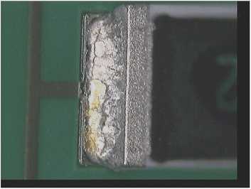
Figurę 1. A 2512-type chip resistor showing cracking in the solder joint.
The work reported here has investigated the suitability of a number of these techniąues to study cracking in lead-free solder joints, and hence their used in assessing joint lifetime. The techniąues studied included micro-sectioning, dye penetration, mechanical tests, and thermal conductivity. Where appropriate FEA analyses have been undertaken to aid in assessing the various tests.
2. Test Specimens
The strength of the solder joints is particularly affected when the assembly contains large components with rigid ceramic bodies soldered to FR4 laminates. In conseąuence, in order to
1
Wyszukiwarka
Podobne podstrony:
NPL Report MATC(A) 164 Cracked area Figurę 6. Crack in a SnAgCu soldcr joint after thcrmal cycling.
NPL Report MATC(A) 164 6.3. 3-Point Bend Test In the 3-point bend test the force was applied to the
NPL Report MATC(A) 164 Finał polishing of the samples was carried out by hand using a gamma aluminid
NPL Report MATC(A) 164 Figurę 5. Central scctioning point shows the microstructurc, but not dcvclopi
NPL Report MATC(A) 164 6. Mechanical Tests Mechanical tests were used to investigate the time-depend
NPL Report MATC(A) 164 The following steps were carried out: • The substratc was c
NPL Report MATC(A) 164A
NPL Report MATC(A) 164 Figurę 12. Test arrangements of resistor specimen. Figurę 13. Predicted major
NPL Report MATC(A) 164 0
NPL Report MATC(A) 164 regime used, the solder becomes accommodating and. irreversible plastic defor
NPL Report MATC(A) 164 curves coincide for displacements less than ~125 pm. For higher levels of dis
NPL Report MATC(A) 164Crack Detection Methods for Lead-free Solder Joints Milos Duśek and Christophe
NPL Report MATC(A) 164 simulate this “worst case” scenario, 2512-type chip resistors and FR4 substra
NPL Report MATC(A) 164 Table 1: Tested temperaturę cycling regimes within ± 4°C of the set
więcej podobnych podstron